Hi all,
Not entirely sure which section this should belong in, but decided to place it here so mods please move if needed.
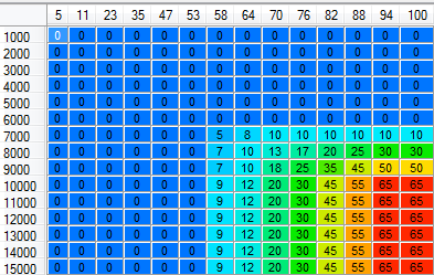
Currently working on several bike engines (still in the bike!) which have secondary injectors mounted in the airbox in a shower form above each throttle body. I know VEMS supports a very basic switch point configuration for secondary injectors, but I was kinda hoping for more. The OEM and other aftermarket ECU's use a 'bias' map for the secondary injectors working with Load and RPM as the axis and a percantage bias figure as the final lookup. So if you had a value of 10% at 70% Throttle and 7000rpm, it would split the fuelling 90% primary and 10% secondary.
Here is a simple version from an R6 ECU.
So my question is kind of a 'is this sort of feature in the current firmware road map?' followed soon after with a 'Is there actually a firmware roadmap???'
I really enjoy using VEMs and would like to bring it to the motec dominated motorbike world if possible, but with every major sports bike using this arrangement, it's kind of hard to push it.
Thanks for any information.
-Gavin

